|
|
||
10/30/07 |
|
|
Mouse to Happs Trackball Hack Many people have already documented their mouse hacks I thought I'd throw mine in as well.
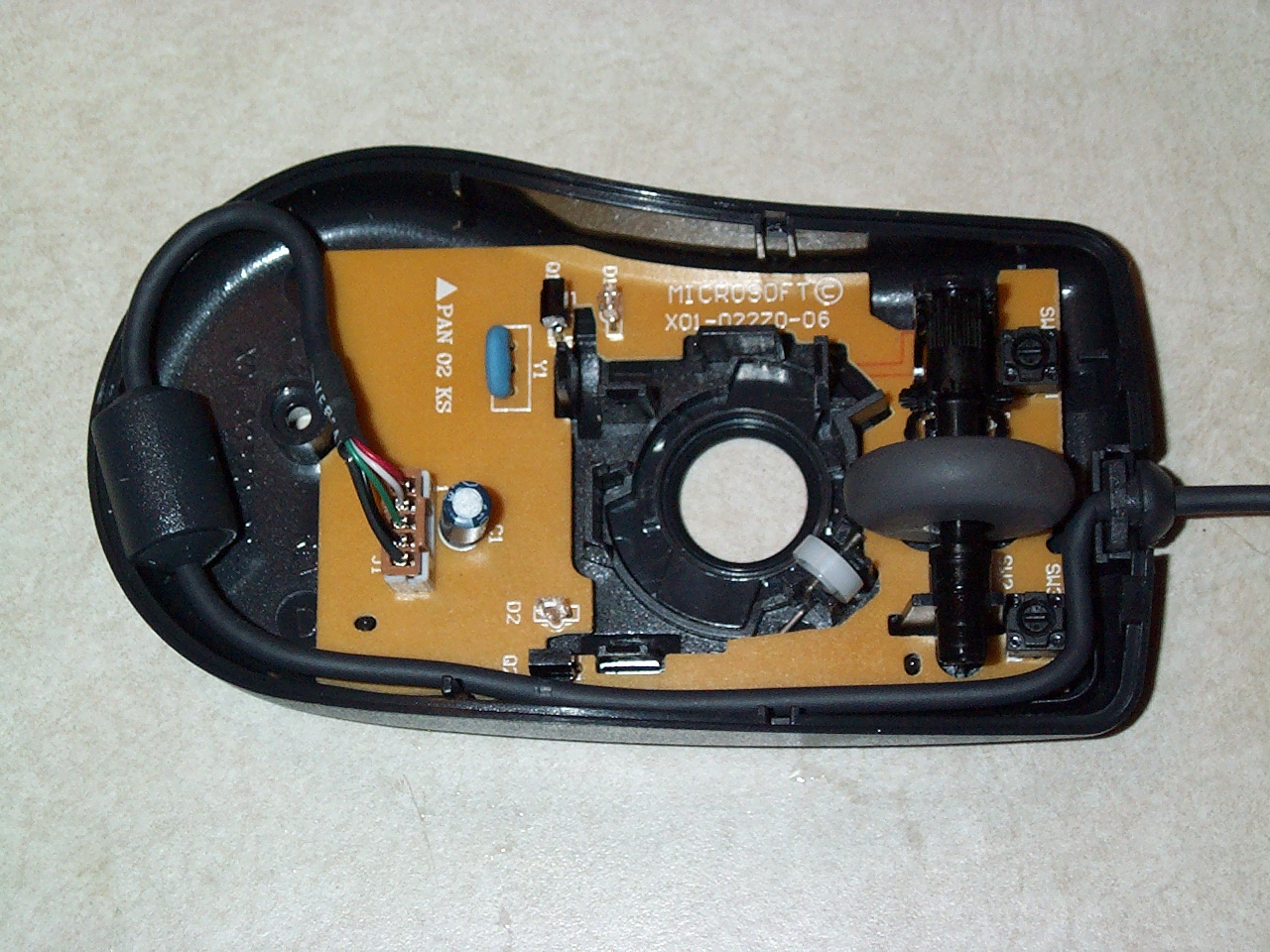
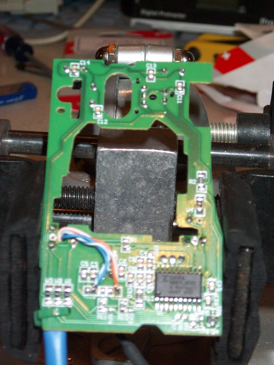
Start with a standard, non optical USB mouse. (The one on the left) You can also hack a optical USB mouse, but only if it uses a separate USB/PS2 encoder in addition to the Agilent optical sensor. One day I'll hack one and post it here, in some ways, its actually easier.
Open the mouse, toss the mouse ball, and the top. Well ok, take out the board, and toss the rest.
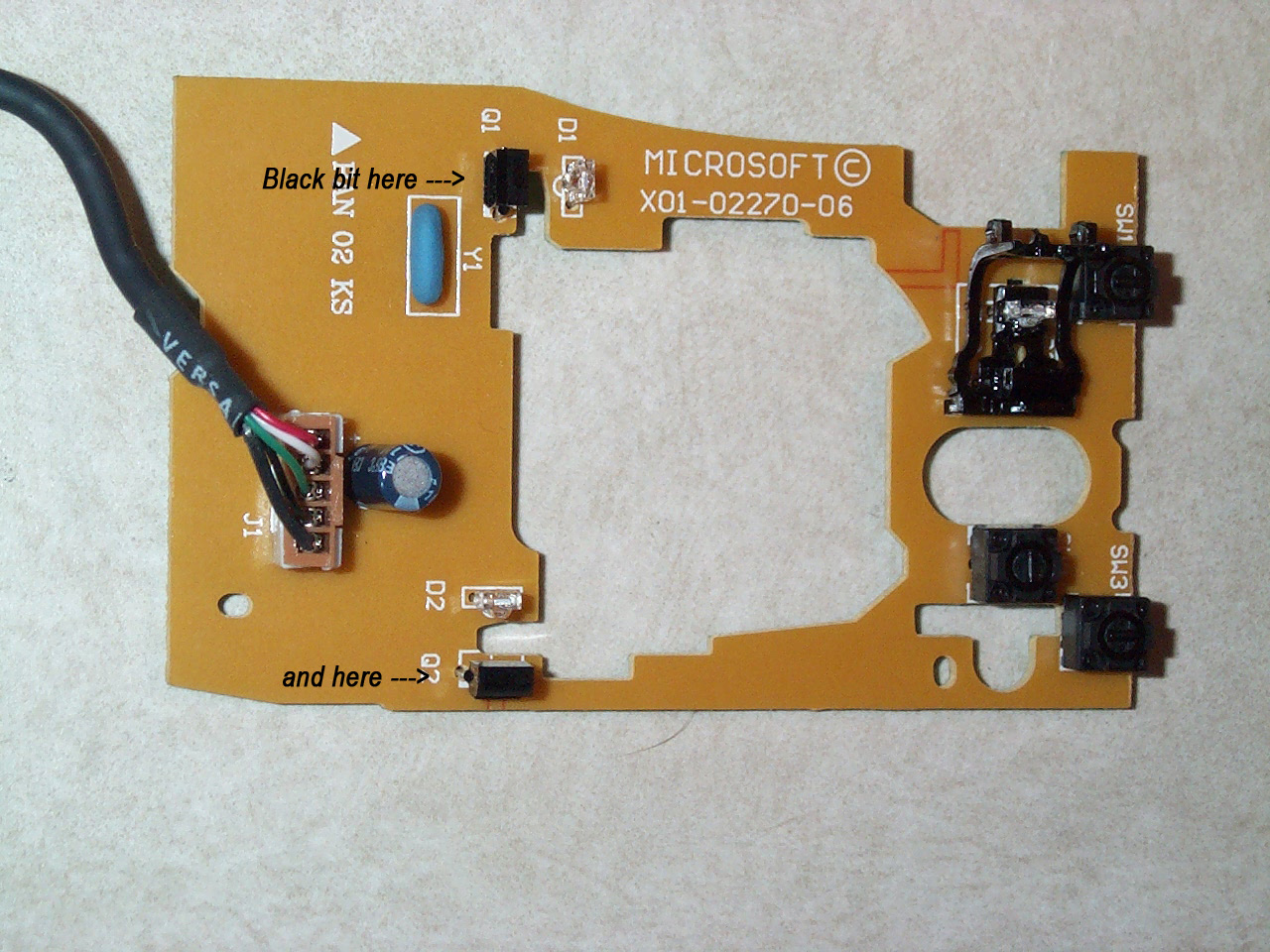
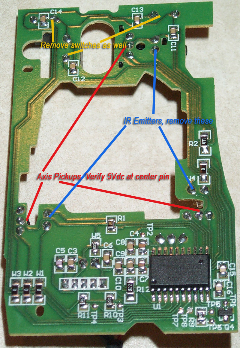
Now you want to remove the black IR recievers, they should be 3 lead, if there are 2 individual pickups, or 4 leads, there are other tutorials to help you. Mines for a standard 3 lead quadrature pickup. Now, remove the 3 lead pickups, the clear ir emitters, and the 3 switches.
Check with the above pic, plus the board into a usb port, and verify 5 volts on the centre pin of the pickup. If its not there, check pins 1&3. Your interested in the other 2 pins. They are where were going to tie the quadrature output from the trackball into.
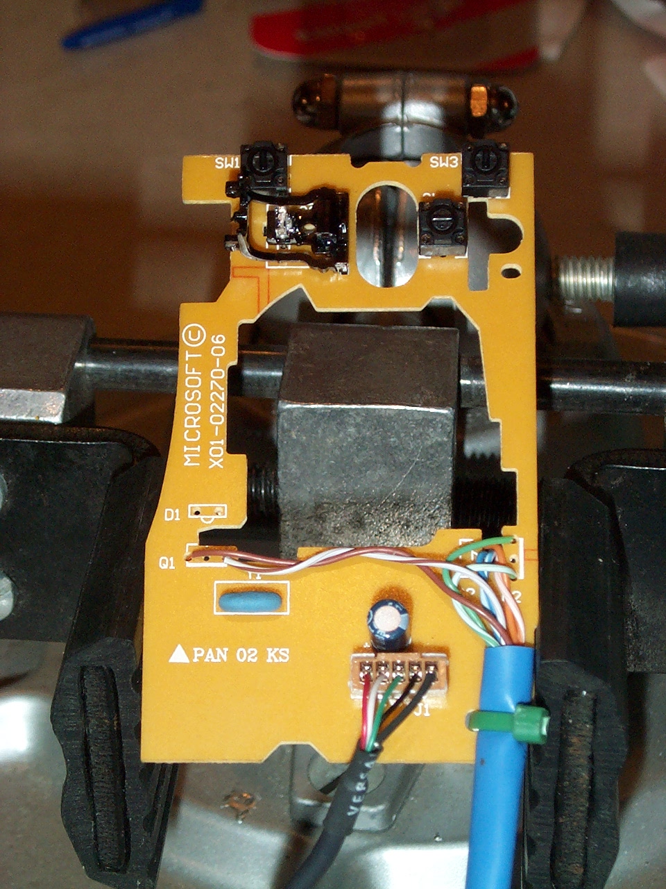
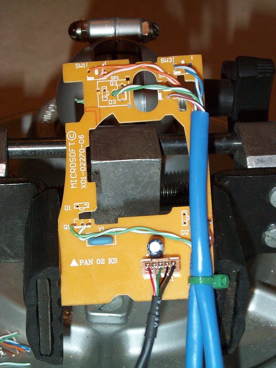
I decided to go with standard CAT5 cable to tie the mouse board into the trackball. Brown pair for the X-axis, green pair for the Y-axis. you want to use the outer 2 holes, and ignore the centre.
Its harder to make out in this pic, but we need to get power for the trackball. You could use the centre pin from one of the pickups, but theres a resistor that needs to be jumped to get enough power to power the trackball. I prefer to get the power from the usb cable connector. Usually it follows standard color codes, but if it doesn't it shouldn't be to hard to figure out. On the microsoft mouse, you have: (Black - Ground) (Red - 5Vdc) (Green - Data +) (White - Data -) and (Braided - Shield) I tied the Blue pair to Ground, and orange pair to 5Vdc. (you don't need to use the whole pair, but I did just to keep from cutting the wires off, and keeping colors straight.
Next is to tie it to the trackball. Pick up a 6 pin 0.93" male connector that matches the one on the Happs trackball, (Molex PN 1261PRT) Crimp the blue pair into one female crimp, the orange into another, the brown and white pair get separated and individually crimped. As well as the green pair. Then plug them into the connector, Blue (ground) pair to Black, Orange (5V) pair to red, Brown pair tie to yellow and green, and green pair tie to purple and blue. As for the phasing of the axis, I didn't worry when I did it, and one of the axis was reversed. I just swapped the connections, and it works fine. Once you plug all the pins into the connector plug, your done!!
Now onto the buttons.
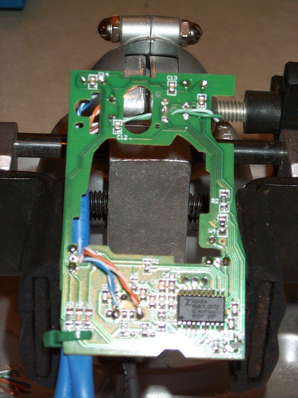
Not alot to do here, got another length of CAT5, Orange pair to the to first button contacts. Blue Pair to the right button, Brown pair to the middle button and green and white pair for future use. (man, that optical encoder there is in just the right spot..... Too bad Mame doesnt have MOUSEWHEEL UP/DOWN support yet...... Would be great for a spinner....... hint..hint..hint..)
Heres a final wiring side pic I took just for the heck of it... Thats it! If you have any questions, just toss me a message using the feedback page. SoundDoc
|
This site was last updated 07/07/04
Copyright © 2004 by Garrett Sloan. All rights reserved.